In this lab experience we'll introduce a new sensor, based on computer vision. The robot is given the same task of experience 2, that is, reaching a goal on a map with moving obstacles, but this time your system will be driven by an omnidirectional vision sensor. In the following, a 4-steps procedure for having a working sensor is described:
Step 1: building an omnidirectional camera
First of all, let's build our omnidirectional camera; all you need is a webcam and an omnidirectional mirror: you should fix them with some adhesive tape, paying attention to correctly align them.
Step2: calibrating your new omnicamera
Exploiting the Ocam Calib toolbox (discussed during the course), you now have to calibrate your camera, and save the calibration data to file.
Step 3: placing your sensor on the robot
You should now fix your sensor to a suitable place on the robot. You can choose any placing you like, but be careful: your choice at this stage will affect results in terms of accuracy and sensitivity. You may want to try several placements before choosing the final one (however, this shouldn't take more than 30 mins!!). How to fix the camera to the robot? When you were a kid, you liked playing with lego, isn't it?!?
Step 4: acquiring images
You can choose between two ways of acquiring images. The first one exploits the VideoCapture class (discussed during the course) directly in your code. An alternative way consists of using the image pipeline available in ROS.
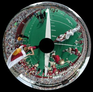
Now, you should be able to acquire images like this one:

At this point, you can start with the real experience, which is divided into two tasks:
Task 1: emulating the IR sensor
In this first case, we'll employ the camera to emulate the IR sensor. This is done by developing a new module that acquires the omnidirectional image and analyzes an appropriate small ROI (Region Of Interest), sending an impulse when it is filled with white pixels. You should be careful in the definition of such ROI, since its location will in turn affect the distance at which the simulated IR sensor will work. Now, go back to the software you developed for the second experience, and substitute the IR sensor module with the one you just developed. This first task is accomplished when you are able to perform the same experiment done in experience 2 with the new sensor. Note that you are not modifying the robot behavior, since you substituted one sensor with a new one providing the same information. In a way, we are exploiting the vision sensor below its capabilities here.
Task 2: fully-featured vision
In this second task you will exploit the whole power of robotic vision. You are asked to develop a module capable of finding the white lines of the map, and evaluating the distance to each of them; moreover, you should also be able to recover the robot orientation with respect to such lines: this turns out to be a very useful feature, since it lets you adjust the robot trajectory very quickly. How to do so? Small hint: you can analyze the image from the center of the mirror going towards the image border, following a given direction. At some point, you will observe the transition between the red carpet and the white line: when this happens, you have found the white line. If you do so on multiple direction, defined, say, every 2°, you will be able to create a map of the white lines around you.
After you developed this module, you will find its output is completely different from what was provided by the IR sensor. This will force you to modify the robot behavior, in order to exploit the new, higher level data provided. This can be either an easy or difficult task, depending on how you designed your software in experience 2. If your design is modular, you will just need to drop some function calls, otherwise...


