Robotica Autonoma
In this lab experience we'll introduce a new sensor, based on computer vision. The robot is given the same task of experience 2, that is, reaching a goal on a map with moving obstacles, but this time your system will be driven by an omnidirectional vision sensor.
You are asked to develop a module capable of finding the white lines of the map, and evaluate the distance of the robot to each of them. Moreover, you should also be able to recover the robot orientation with respect to such lines: this turns out to be a very useful feature, since it lets you adjust the robot trajectory very quickly.
After you developed the requested module, you will see that its output is completely different from what was provided by the IR sensor. This will push you to modify the robot behavior, in order to exploit the new, higher level data provided. This can be either an easy or difficult task, depending on how you designed your software in experience 2. If your design is modular, you will just need to drop some function calls, otherwise...
At the end of the experience...
Objectives
- Calibrate the omnidirectional camera by means of OCamCalib
- Exploit the omnidirectional camera: extract information using computer vision algorithms
- Exploit calibration data to evaluate 3D information
- Make the robot reach the goal or report if it is not reachable (as in experience 2)
Plus
- Reuse your code as much as possible
- Organize camera acquisition into a separate ROS module
- Detect obstacles and measure their distance to the robot
Challenges
- Develop your first computer vision algorithms
- Handle calibration
What we want
- Code (BitBucket)
- Video (YouTube or BitBucket) -- including a video of the output of your computer vision algorithms
- Report (PDF using Moodle) containing at least
- The algorithm overview
- Description of all steps of your vision algorithm
- The role of each node you developed
- The three nodes interaction
- The parameter file/launcher description
- The CMakeLists.txt description
Given two obstacles, make the robot go around the first one and stops 3 cm behind the second one for 10 seconds and finally come back, as in Figure 1.

At the end of the experience...
Objectives
- Make the robot reach the second obstacle
- Go back to the starting position
- Understand the basic ROS concepts (launcher, compiler and publisher/subscriber)
Plus
- Use the thrid engine to move the ultrasonic sensor
- Object Oriented (OO) approach
Challenges
- Unknow distance between the two obstacles
What we want
- Code (BitBucket)
- Video (YouTube or BitBucket)
- Report (PDF using Moodle) containing
- The algorithm overview
- The procedures to make the robot go straight and turn
- What are the main robot problems and why
- The Launcher description
- The CMakeLists.txt description
Explanation
Preliminary steps
cd ~/Workspace/Groovy/catkin_ws/src
svn co --username ros \
https://robotics.dei.unipd.it/svn/iaslab/projects/robots/nxt .
rm -rf .svn
catkin_make --force-cmake -G"Eclipse CDT4 - Unix Makefiles"

roslaunch nxt_unipd nxt_lab.launch
roslaunch nxt_unipd teleop_keyboard.launch
Robot configuration
nxt_lab.yaml
 -  type: ultrasonic
    frame_id: ultrasonic_link
    name: ultrasonic_sensor
    port: PORT_4
    spread_angle: 0.2
    min_range: 0.01
    max_range: 2.5
    desired_frequency: 5.0
Program launcher
nxt_lab.launch
  <group ns="base_parameters">
    <param name="r_wheel_joint" value="r_wheel_joint"/>
    <param name="l_wheel_joint" value="l_wheel_joint"/>
    <param name="wheel_radius" value="0.022"/>
    <param name="wheel_basis" value="0.055"/>
    <param name="vel_to_eff" value="0.2"/>
    <param name="l_vel_to_eff" value="0.1"/>
    <param name="r_vel_to_eff" value="0.1"/>
  </group>
Robot controller
advanced_control.py
{tex}v_{trans}^{est} \left[i+1\right] = \frac{1}{2} \left( v_{trans}^{est}\left[i\right] + \frac{1}{2} \left( v_{rot}^{reg}\left[i,j_{wheel}^{l} \right] + v_{rot}^{reg}\left[i,j_{wheel}^{r} \right] \right) r_{wheel} \right){/tex}
{tex}v_{rot}^{est} \left[i+1\right] = \frac{1}{2} \left( v_{rot}^{est}\left[i\right] + \frac{1}{2} \left( v_{rot}^{reg}\left[i,j_{wheel}^{l} \right] - v_{rot}^{reg}\left[i,j_{wheel}^{r} \right] \right) \frac{r_{wheel}}{b_{wheel}} \right){/tex}
where:
{tex}v_{trans}^{est} \left[i\right]{/tex} is the estimated translational velocity at the instant{tex}i_{.}{/tex}
{tex}v_{rot}^{est} \left[i\right]{/tex} is the estimated rotational velocity at the instant{tex}i_{\qquad}{/tex}
{tex}v_{rot}^{reg}\left[i,j_{wheel}^{l} \right]{/tex} is the registered rotational velocity for the joint of the left wheel at the instant{tex}i_{\qquad}{/tex}
{tex}v_{rot}^{reg}\left[i,j_{wheel}^{r} \right]{/tex} is the registered rotational velocity for the joint of the right wheel at the instant{tex}i_{\qquad}{/tex}
{tex}r_{wheel}{/tex} is the wheel radius
{tex}b_{wheel}{/tex} is the wheel basis
{tex}v_{trans}^{cmd} \left[i+1\right] = v_{trans}^{des}\left[i\right] + k_{trans} \left( v_{trans}^{des}\left[i \right] - v_{trans}^{est}\left[i +1 \right] \right){/tex}
{tex}v_{rot}^{cmd} \left[i+1\right] = v_{rot}^{des}\left[i\right] + k_{rot} \left( v_{rot}^{des}\left[i \right] - v_{rot}^{est}\left[i \right] \right){/tex}
where:
{tex}v_{trans}^{cmd} \left[i\right]{/tex} is the translational velocity applied to the joint at the instant{tex}i_{.}{/tex}
{tex}v_{rot}^{cmd} \left[i\right]{/tex} is the rotational velocity applied to the joint at the instant{tex}i_{.}{/tex}
{tex}v_{trans}^{des}\left[i \right]{/tex} is the desired transational velocity for the joint at the instant{tex}i_{.}{/tex}
{tex}v_{rot}^{des}\left[i \right]{/tex} is the desired rotational velocity for the joint at the instant{tex}i_{.}{/tex}
{tex}k_{trans}{/tex} is the trasational constant
{tex}k_{rot}{/tex} is the rotational constant
{tex}F \left[i+1\right] = k_v^F \left( v_{trans}^{cmd}\left[i + 1\right] \frac{1}{r_{wheel}} - v_{rot}^{cmd}\left[i +1 \right] \frac{b_wheel}{r_{wheel}} \right){/tex}
where:
F \left[i\right] is the effort applied to the joint at the instant{tex}i_{.}{/tex}
k_v^Fis the constant to transform velocity to effort
Robot teleoperation
nxt_key.cpp
    switch(c)
    {
      case KEYCODE_L:
        ROS_DEBUG("LEFT");
        angular_ = 2.0;
        break;
      case KEYCODE_R:
        ROS_DEBUG("RIGHT");
        angular_ = -2.0;
        break;
      case KEYCODE_U:
        ROS_DEBUG("UP");
        linear_ = 0.15;
        break;
      case KEYCODE_D:
        ROS_DEBUG("DOWN");
        linear_ = -0.15;
        break;
    }
teleop_keyboard.launch
<node pkg="nxt_unipd" type="nxt_teleop_key" name="nxt_teleop_key"  output="screen">
  <param name="scale_linear" value="1" type="double"/>
  <param name="scale_angular" value="1" type="double"/>
</node>
Sensors messages
Header header
float64 range
float64 range_min
float64 range_max
float64 spread_angle
Laboratory experiences
Here you can find some links to help you in your lab experience:
Install ROS Base System (with Lego NXT packages)
1. Install Ubuntu 13.04 64bit
Download and install the ISO from here.
2. Install ROS Hydro
2.1 Setup Sources
sudo sh -c 'echo "deb http://packages.ros.org/ros/ubuntu raring main" \
> /etc/apt/sources.list.d/ros-latest.list'
wget http://packages.ros.org/ros.key -O - | sudo apt-key add -
2.2 Installation
Make sure everything is up to date.
sudo apt-get update
sudo apt-get upgrade
Install all needed packages.
sudo apt-get install \
`wget http://robotics.dei.unipd.it/images/teaching/hydro.list -O - | cat -`
Initialize rosdep to easily install system dependencies.
sudo rosdep init
rosdep update
3. System Setup
3.1 Set USB permits
sudo groupadd lego
sudo usermod -a -G lego `id -u -n`
echo 'SUBSYSTEM=="usb", ATTRS{idVendor}=="0694", GROUP="lego", MODE="0660"
SUBSYSTEM=="usb", ATTRS{idVendor}=="1962", GROUP="lego", MODE="0660"' \
| sudo tee /etc/udev/rules.d/99-lego.rules
sudo restart udev
Now log out and log back in to finish. A more detailed version of these instructions are at NXT-Python.
3.2 Setup OpenNI + NITE
The OpenNI framework is an open source SDK used for the development of 3D sensing middleware libraries and applications. In order to setup this library type
cd ~/Downloads
wget http://www.openni.org/wp-content/uploads/2012/12/NITE-Bin-Linux-x64-v1.5.2.21.tar.zip
unzip NITE-Bin-Linux-x64-v1.5.2.21.tar.zip
tar -xjvf NITE-Bin-Linux-x64-v1.5.2.21.tar.bz2
cd NITE-Bin-Dev-Linux-x64-v1.5.2.21
sudo ./uninstall.sh
sudo ./install.sh
3.3 Setup libhid
libhid is a user-space HID access library written in C. We use it to control a connected Robovie-X. In order to setup this library install the deb packages you can find here or type
sudo apt-get install libusb-dev
cd ~/Downloads
wget --tries=10 http://alioth.debian.org/frs/download.php/1958/libhid-0.2.16.tar.gz
tar xzf libhid-0.2.16.tar.gz
cd libhid-0.2.16
./configure --enable-werror=no
make
sudo make install
sudo ldconfig
3.4 Setup ROS
Now we create two separate workspaces to use both catkin and rosbuild. See this tutorial for a more complete explanation.
source /opt/ros/hydro/setup.bash
mkdir -p ~/Workspace/ros/catkin_ws/src
cd ~/Workspace/ros/catkin_ws
catkin_make --force-cmake
mkdir -p ~/Workspace/ros/rosbuild_ws
rosws init ~/Workspace/ros/rosbuild_ws ~/Workspace/ros/catkin_ws/devel
echo "source ~/Workspace/ros/rosbuild_ws/setup.bash" >> ~/.bashrc
4. Programming tools
4.1 Eclipse
The Eclipse package we're going to install is an IDE for C/C++ developers with Mylyn integration.
Download Eclipse from this link or check for the latest version (actually is Kepler) at www.eclipse.org/downloads.
We first need Java (Oracle or OpenJDK is the same).
If it is not installed, i.e
java -version
raises some errors, type
sudo apt-get purge openjdk*
sudo add-apt-repository ppa:webupd8team/java
sudo apt-get update
sudo apt-get install oracle-jdk7-installer
Then, install Eclipse
cd ~/Downloads
tar -xzf eclipse-cpp-*
sudo mv eclipse /opt
sudo chown -R root:root /opt/eclipse
Finally setup Ubuntu/Unity.
sudo ln -s /opt/eclipse/eclipse /usr/local/bin
echo '[Desktop Entry]
Name=Eclipse
Type=Application
Exec=bash -i -c "eclipse"
Terminal=false
Icon=/opt/eclipse/icon.xpm
Comment=Integrated Development Environment
NoDisplay=false
Categories=Development;IDE' | sudo tee /usr/share/applications/eclipse.desktop
To completely remove Eclipse use the following commands.
sudo rm -rf /opt/eclipse
sudo rm -f /usr/local/bin/eclipse
sudo rm -f /usr/share/applications/eclipse.desktop
In this experience you have to control a humanoid robot in order to reproduce human motion captured by an RGB-D sensor like Microsoft Kinect. In practice, you have to apply and adapt the knowledge acquired in the fourth experience to a real robot: the Robovie-X (Figure 1).

Developing your code, take care of the differences between simulated and real system and describe your feeling in your reports.
The package used to move the Robovie-X is robovie_x_controller. It is precompiled and you cannot look at this package code. It receive a JointState message and so you can try it using the joint_state_pubblisher you saw during last experience. To download this package follow these instructions:
cd projects
svn co --username ros \
https://robotics.dei.unipd.it/svn/iaslab/projects/robots/RobovieX/robovie_x_controller
rospack profile && rosstack profile
Since it is precompiled there is no need to build it.
If you have a 32bit operating system running on your pc, use the following instructions before to run the controller.
roscd robovie_x_controller/bin
rm robovie_controller
ln -s x86/robovie_controller robovie_controller
You can try the application using:
roslaunch robovie_x_model xacrodisplay.launch
rosrun robovie_x_controller robovie_controller
Once your robot respond well at your movements, try to make it walk.
In this lab experience we'll introduce a humanoid robot, the Robovie-X, and the use of an XBOX 360 Kinect sensor to record some human movements that will be remapped into and reproduced by the robot. On one hand, we'll use a Kinect sensor for the data acquisition, on the other hand we'll use rviz and Gazebo tools to reproduce the human recorded poses through the robot.
In the following, the procedure for having a working tool is described:
Step 1: Setup and test Kinect and skeleton tracker
First of all, we have to create our workspace:
cd projects
mkdir ActionModel
cd ActionModel
svn co --username ros \
https://robotics.dei.unipd.it/svn/iaslab/projects/ActionModel/src .
Now lets make sure that ROS can find your new package. It is often useful to call rospack profile after making changes to your path so that new directories will be found:
rospack profile && rosstack profile
roscd ActionModel
cmake -G"Eclipse CDT4 - Unix Makefiles"
rosmake
Run the ActionModel plugin from a "launch" file:
roslaunch ActionModel openni_tracker.launch
If all run correctly, you should get something like this:
...
frame id = openni_rgb_optical_frame
rate = 30
file = /opt/ros/electric/stacks/unipd-ros-pkg/ActionModel/config/tracker.xml
InitFromXml... ok
Find depth generator... ok
Find user generator... ok
StartGenerating... ok
...
Now, if a person goes in front of the camera, a new user is identify. In order to calibrate the system and track the user with respect to the Kinect, the person have to assume a "Psi Pose" like in Figure 1.
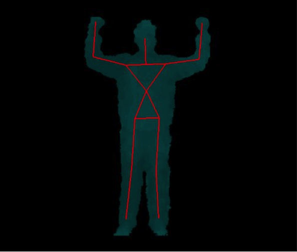
If all run correctly you see:
...
New User 1
Pose Psi detected for user 1
Calibration started for user 1
Calibration complete, start tracking user 1
Visualize the tracked person by starting the :
rosrun rviz rviz
and setup some basic properties:
- Fixed frame: /openni_camera
- Add: pointCloud2
- Topic: /camera/rgb/points
- ColorTransform: RGB8
- Style: points
- Add: TF
You should see something like this:
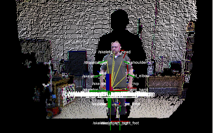
This package provides a set of tools for recording from and playing back to ROS topics. You will use it to record tf trasforms.
Task 1: Remapping of the human joints into the correspondent ones of the Robovie-X
tf is a package that lets the user keep track of multiple coordinate frames over time. tf maintains the relationship between coordinate frames in a tree structure buffered in time, and lets the user transform points, vectors, etc. between any two coordinate frames at any desired point in time, and allows you to ask questions like:
- Where was the head frame relative to the world frame, 5 seconds ago?
- What is the pose of the object in my gripper relative to my base?
- What is the current pose of the base frame in the map frame?
You have to write a tf listener (C++) through which get access to frame transformations.
Suggestion:
#include <tf/transform_listener.h>
...
...
...
tf::TransformListener listener;
  ros::Rate rate(10.0);
  while (node.ok()){
    tf::StampedTransform transform;
    try{
      listener.lookupTransform("/robovieX2", "/robovieX1",
                               ros::Time(0), transform);
    }
    catch (tf::TransformException ex){
      ROS_ERROR("%s",ex.what());
    }
    ...
  }
...
You will use it in conjunction with the joint_state_publisher in the next task in order to exploit these data to control the robot in Gazebo.
Task 2: Test your Robovie-X in Gazebo
Setup your workspace environment by downloading the robovie_x_gazebo_plugin and robovie_x_model plugins.
cd projects
svn co --username ros \
https://robotics.dei.unipd.it/svn/iaslab/projects/robots\
/RobovieX/robovie_x_gazebo_plugin
svn co --username ros \
https://robotics.dei.unipd.it/svn/iaslab/projects/robots\
/RobovieX/robovie_x_model
Build and launch your packages:
rospack profile && rosstack profile
roscd robovie_x_gazebo_plugin
cmake -G"Eclipse CDT4 - Unix Makefiles"
rosmake
roscd robovie_x_model
cmake -G"Eclipse CDT4 - Unix Makefiles"
rosmake
roslaunch robovie_x_gazebo_plugin gazebo_robot.launch
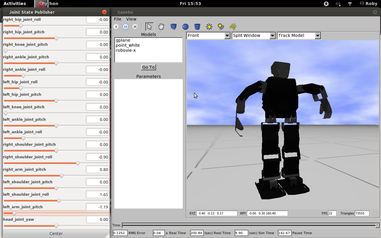
You have to become practical with the GUI, the robot model and to explore the mechanism control underlying the movement.
Task 3: Move the Robovie-X using data acquired through Kinect
You have to control the Robovie-X model into Gazebo by using the joint_state_publisher plugin through the sensor_msgs/JointState:
Header header
string[] name
float64[] position
float64[] velocity
float64[] effort
A node for publishing joint angles, either through a GUI, or with default values. This package publishes sensor_msgs/JointState messages for a robot. The package reads the robot_description parameter, finds all of the non-fixed joints and publishes a JointState message with all those joints defined.
The joint angles published from joint_state_publisher will be listened from tf listener and sent to the robot controller to move each non-fixed joint.
Suggestion: start from the upper body part.
That's all, have fun!!!
In this lab experience we'll introduce a new sensor, based on computer vision. The robot is given the same task of experience 2, that is, reaching a goal on a map with moving obstacles, but this time your system will be driven by an omnidirectional vision sensor. In the following, a 4-steps procedure for having a working sensor is described:
Step 1: building an omnidirectional camera
First of all, let's build our omnidirectional camera; all you need is a webcam and an omnidirectional mirror: you should fix them with some adhesive tape, paying attention to correctly align them.
Step2: calibrating your new omnicamera
Exploiting the Ocam Calib toolbox (discussed during the course), you now have to calibrate your camera, and save the calibration data to file.
Step 3: placing your sensor on the robot
You should now fix your sensor to a suitable place on the robot. You can choose any placing you like, but be careful: your choice at this stage will affect results in terms of accuracy and sensitivity. You may want to try several placements before choosing the final one (however, this shouldn't take more than 30 mins!!). How to fix the camera to the robot? When you were a kid, you liked playing with lego, isn't it?!?
Step 4: acquiring images
You can choose between two ways of acquiring images. The first one exploits the VideoCapture class (discussed during the course) directly in your code. An alternative way consists of using the image pipeline available in ROS.
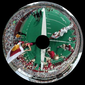
Now, you should be able to acquire images like this one:

At this point, you can start with the real experience, which is divided into two tasks:
Task 1: emulating the IR sensor
In this first case, we'll employ the camera to emulate the IR sensor. This is done by developing a new module that acquires the omnidirectional image and analyzes an appropriate small ROI (Region Of Interest), sending an impulse when it is filled with white pixels. You should be careful in the definition of such ROI, since its location will in turn affect the distance at which the simulated IR sensor will work. Now, go back to the software you developed for the second experience, and substitute the IR sensor module with the one you just developed. This first task is accomplished when you are able to perform the same experiment done in experience 2 with the new sensor. Note that you are not modifying the robot behavior, since you substituted one sensor with a new one providing the same information. In a way, we are exploiting the vision sensor below its capabilities here.
Task 2: fully-featured vision
In this second task you will exploit the whole power of robotic vision. You are asked to develop a module capable of finding the white lines of the map, and evaluating the distance to each of them; moreover, you should also be able to recover the robot orientation with respect to such lines: this turns out to be a very useful feature, since it lets you adjust the robot trajectory very quickly. How to do so? Small hint: you can analyze the image from the center of the mirror going towards the image border, following a given direction. At some point, you will observe the transition between the red carpet and the white line: when this happens, you have found the white line. If you do so on multiple direction, defined, say, every 2°, you will be able to create a map of the white lines around you.
After you developed this module, you will find its output is completely different from what was provided by the IR sensor. This will force you to modify the robot behavior, in order to exploit the new, higher level data provided. This can be either an easy or difficult task, depending on how you designed your software in experience 2. If your design is modular, you will just need to drop some function calls, otherwise...
Given a map composed of nxm squares, make the robot go from a Start square to a Goal square while avoiding obstacles. You can see an example of map in Figure 1.
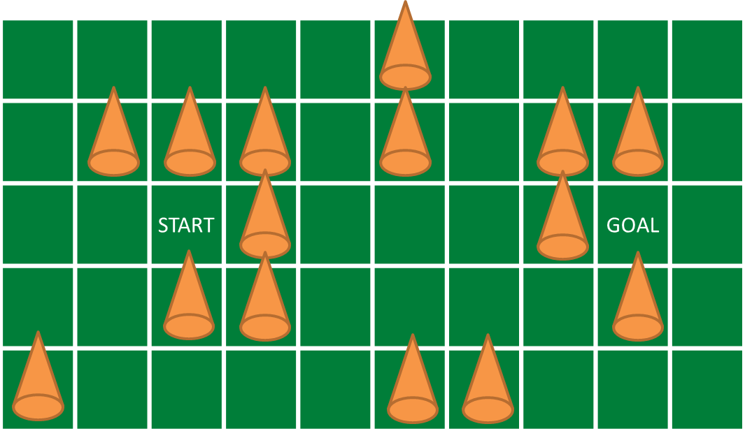
The robot can only go in the north, south, east and west squares, namely it cannot move diagonally. In the first scenario the map is fixed so you know where the obstacles are. In the second scenario the map can change, so you cannot assume to know it in advance. Video 1 shows a possible procedure to reach the goal.
http://robotics.dei.unipd.it/images/video/exp2.m4v
At the end of the experience...
Objectives
- Make the robot reach the goal or report if it is not reachable
- Use the infrared sensor
- Create more then one node (at least three: Robot, Navigation, Mapping)
- Read the map parameters from a file (.yaml) or the launcher (as args)
- Understand the basic ROS concepts (node parameters, use of topics)
Plus
- Use the third engine to move the ultrasonic sensor
- Object Oriented (OO) approach
- Draw the map (e.g. using OpenCV)
- Assume that the obstacles are not fixed. That is, if the goal seem not to be reachable, try again paths already tested.
Challenges
- Solve a known a priori map, given the start and goal cells
- The map is unknown (you don't know where the obstacles are, you only know the start and goal cells)
What we want
- Code (BitBucket)
- Video (YouTube or BitBucket)
- Report (PDF using Moodle) containing at least
- The algorithm overview
- At each step, how you choose the next cell to move in and why
- The role of each node you developed
- The three nodes interaction
- The parameter file/launcher description
- The CMakeLists.txt description
Sensors messages
Header header
float64 intensity
float64 r
float64 g
float64 b
Given a map composed of nxm squares, make the robot go from a Start square to a Goal square while avoiding obstacles. You can see an example of map in Figure 1.

The robot can only go in the north, south, east, west squares, namely it cannot move diagonally. In the first scenario the map is fixed so you know where the obstacles are. In the second scenario the map can change, so you cannot assume to know it in advance. Video 1 shows a possible procedure to reach the goal.
http://robotics.dei.unipd.it/images/video/exp2.m4v
As a plus, once the robot has reached the Goal square, you have to make it push a touch sensor connected to another NXT Brick. The purpose of this part of the experience is to communicate between two different NXT Bricks using ROS. In order to do this, you have to create a new simple robot configuration starting from the .yaml file you can find in nxt_unipd package and this NXT ROS tutorial. Once your package is ready and tested you have to connect the two NXT Bricks to different computers. In the first computer run your path planning algorithm, in the second make ROS search for master at the first one location:
export ROS_MASTER_URI=http://first_IP_adress:11311
Now all ROS programs you launch in the second computer are connected to the first one and they can look at each other topics.
Sensors messages
Header header
float64 intensity
float64 r
float64 g
float64 b
Header header
bool contact
Install a ROS base system to your computer. These settings will be used for Robotica Autonoma laboratory.


